Practice Makes Perfect
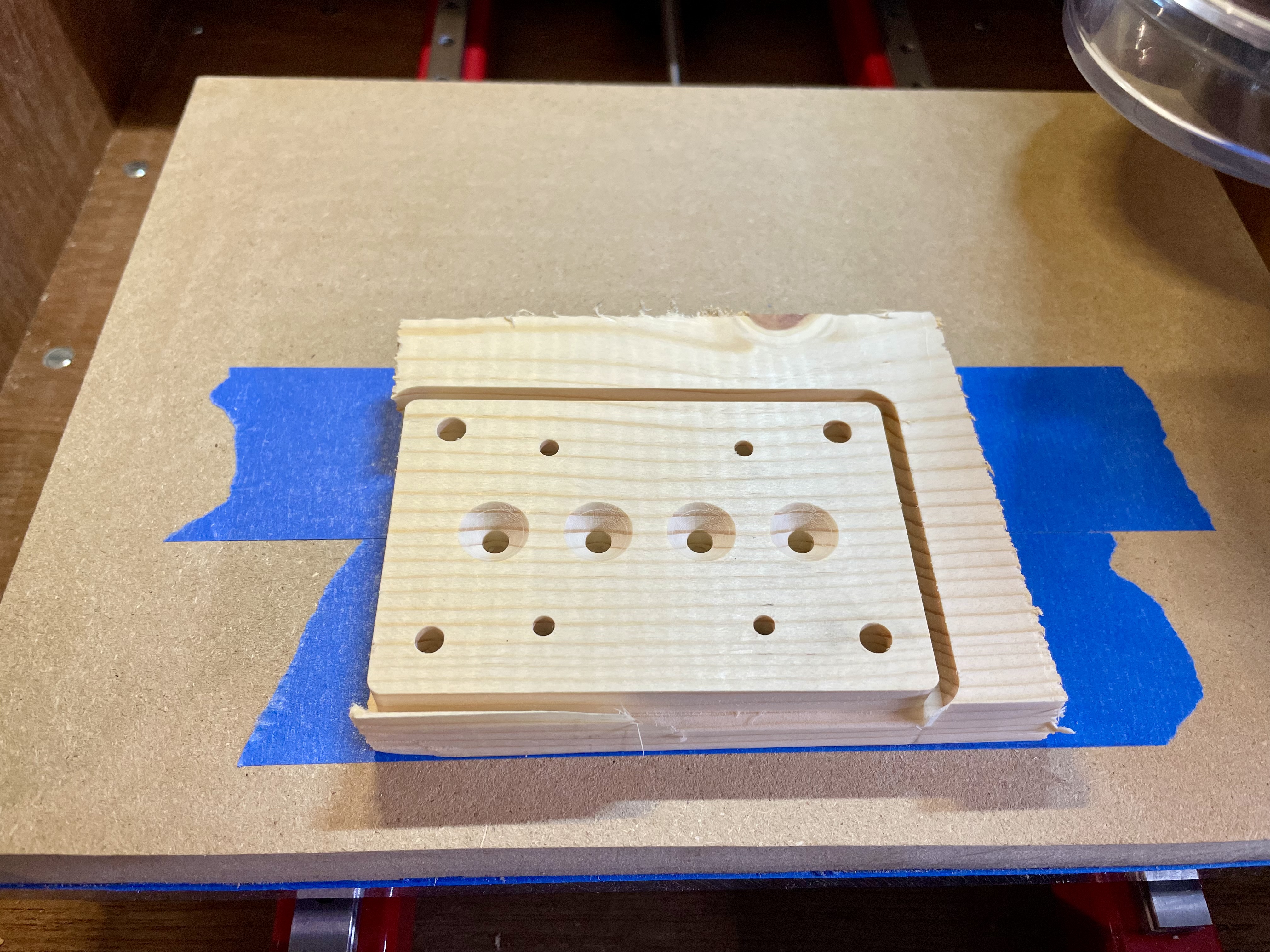
Being so very new to all this, as I prepared to replace the 3D printed parts in the Z axis with aluminum parts machined from 6061 aluminum, I made practice parts in wood.
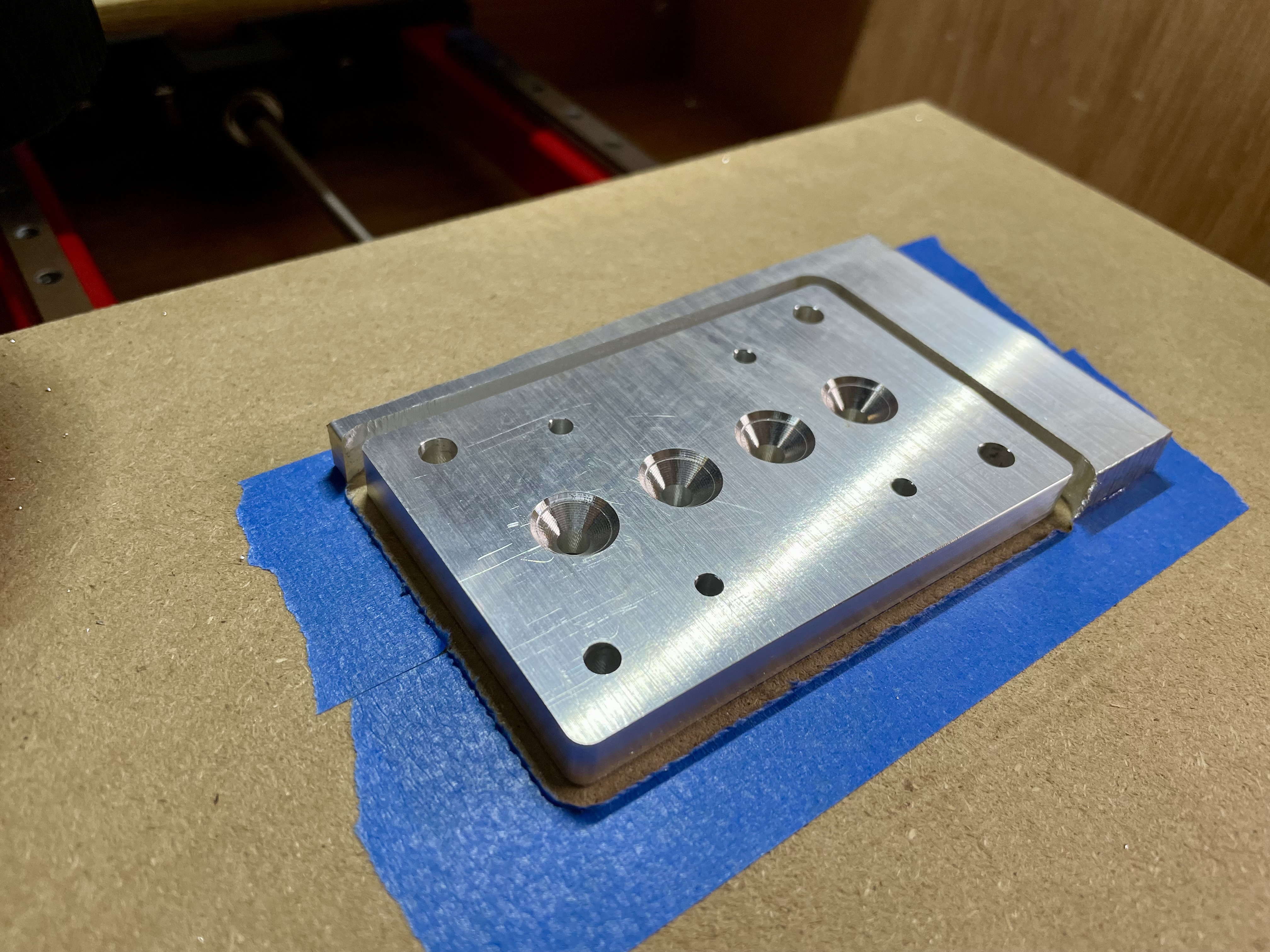
Thankfully, this worked very well. One of the items you’ll see is that I was able to use painters tape and CA glue as the workholding method. This works great for sheet material – either wood or aluminum, as long as the surface is flat. It greatly eases the machining configuration as you don’t need to worry about building tool paths in your CAM software to avoid clamps.
Starting with this:  Soon yields this:
Not everything goes smoothly.
Lots of time during this stage is spent in Fusion 360 figuring out toolpaths. As Joe, the MilkCr8 designer says, “this project is designed to force you to learn.” He’s got that right.
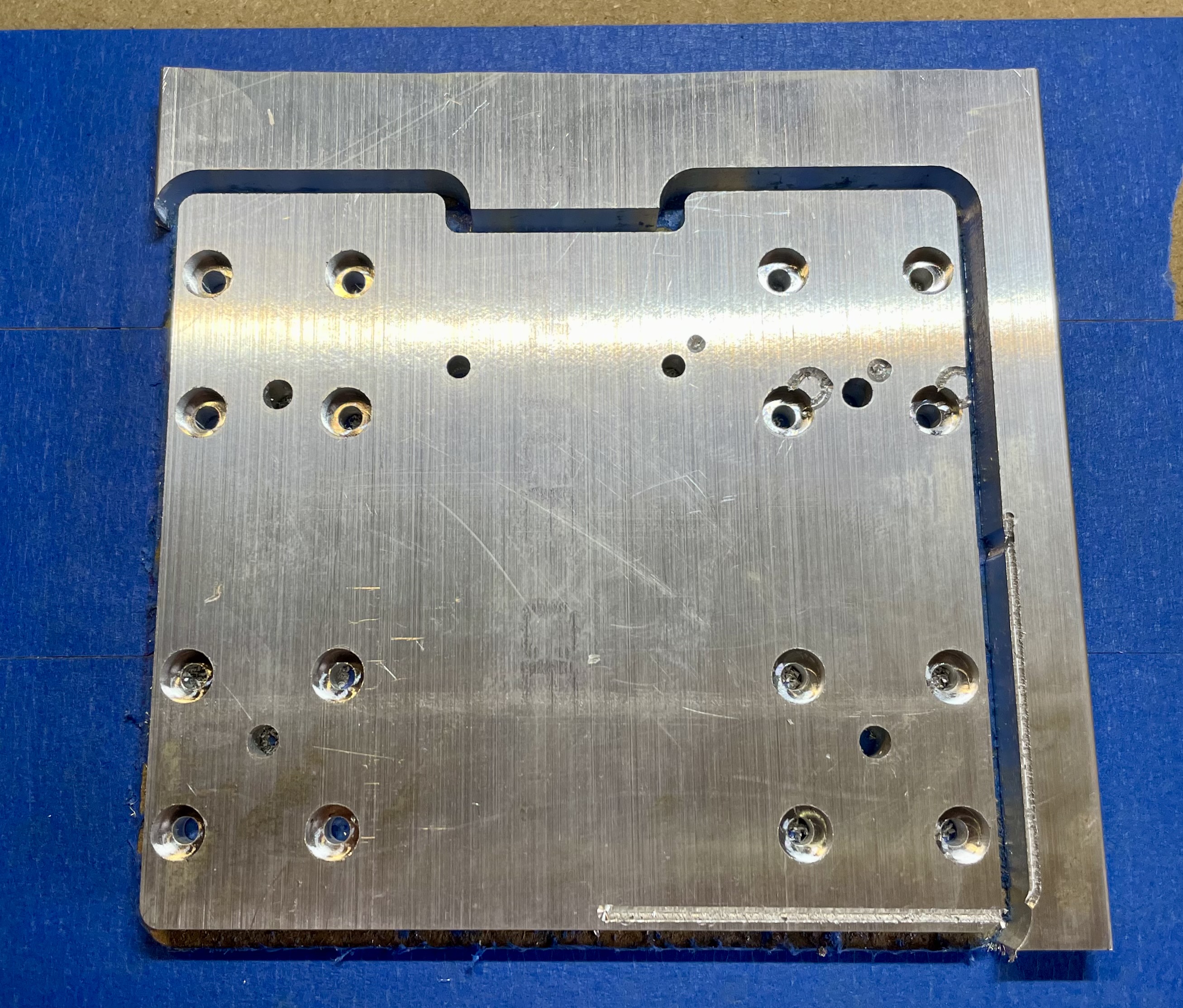
First Oops
On the Z plate, I had completed all the critical cuts, and had just switched the end mill from a standard end mill to a chamfer end mill to give the edge a nice bevel. Unfortunately, I reset my X and Y zero positions when I wasn’t supposed to – and I set them to the already trimmed corner! This moved XY by about 4mm. You can see the incorrect cuts at the right side and bottom right of the piece. I was able to stop the operation before it got further. After some salty language, I decided to live with the error as a good reminder to measure twice and cut once.
