Leveling the SpoilBoard
Once you’ve cut your first piece, it is common to see some repeating lines in the top surface of your workpiece. These indicate that the endmill cut is not completely perpendicular to the work surface. You can greatly improve this situation by tramming your machine to ensure your spindle/endmill is as close to perpendicular as possible.
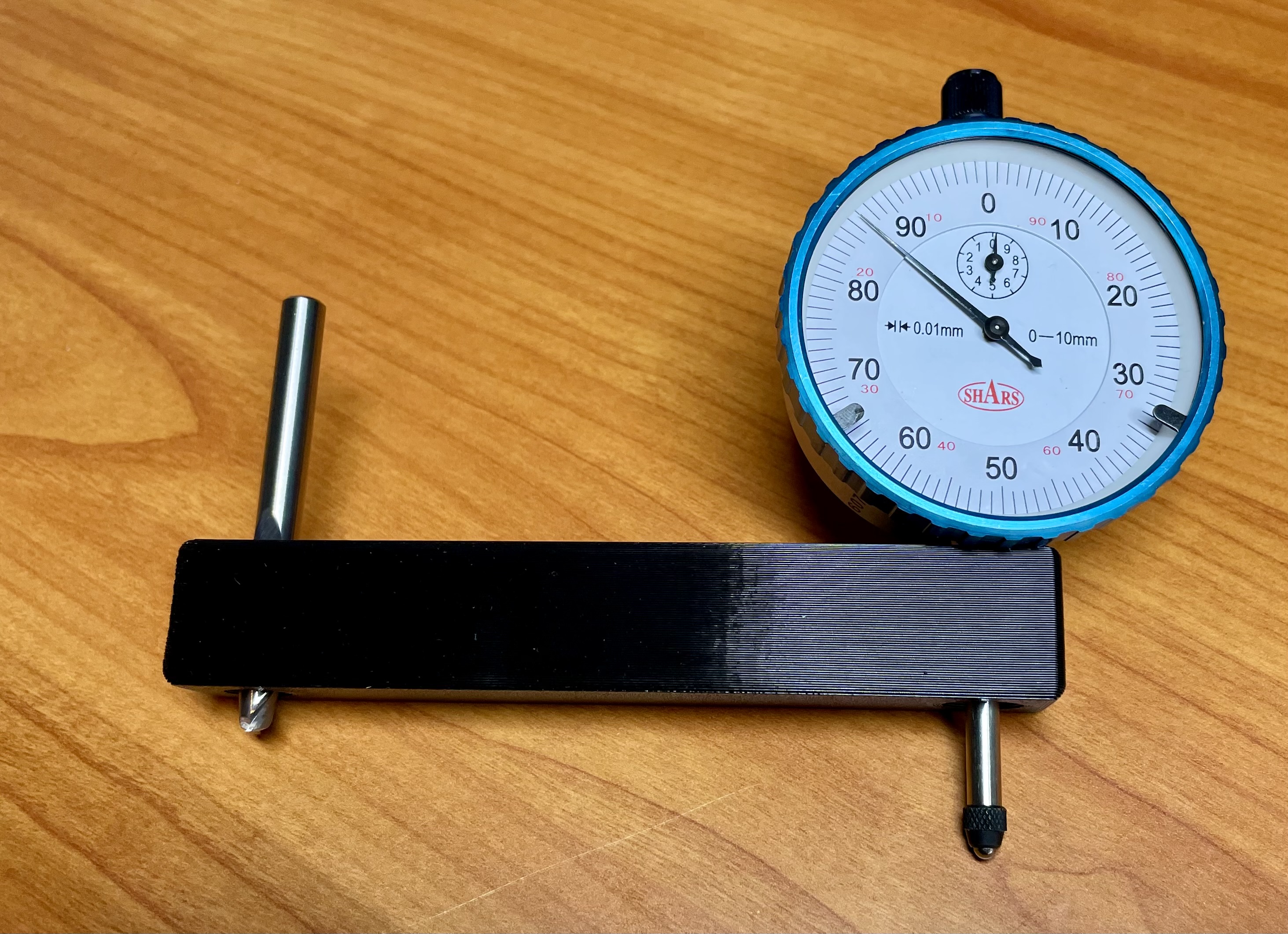
First step is to attempt to measure height differences between all four sides of the spindle. I 3D printed a jig to hold my dial indicator. Manually spinning this around on the MDF wasteboard helped to indcate where things where high or low.

In the future, I plan to create a spoilboard that has embedded threaded nuts to allow different methods of workholding to hold stock to the spoilboard.

Here is my first attempt at leveling the spoilboard surface to match that of the router/spindle as it travels across the X-axis. Take a look
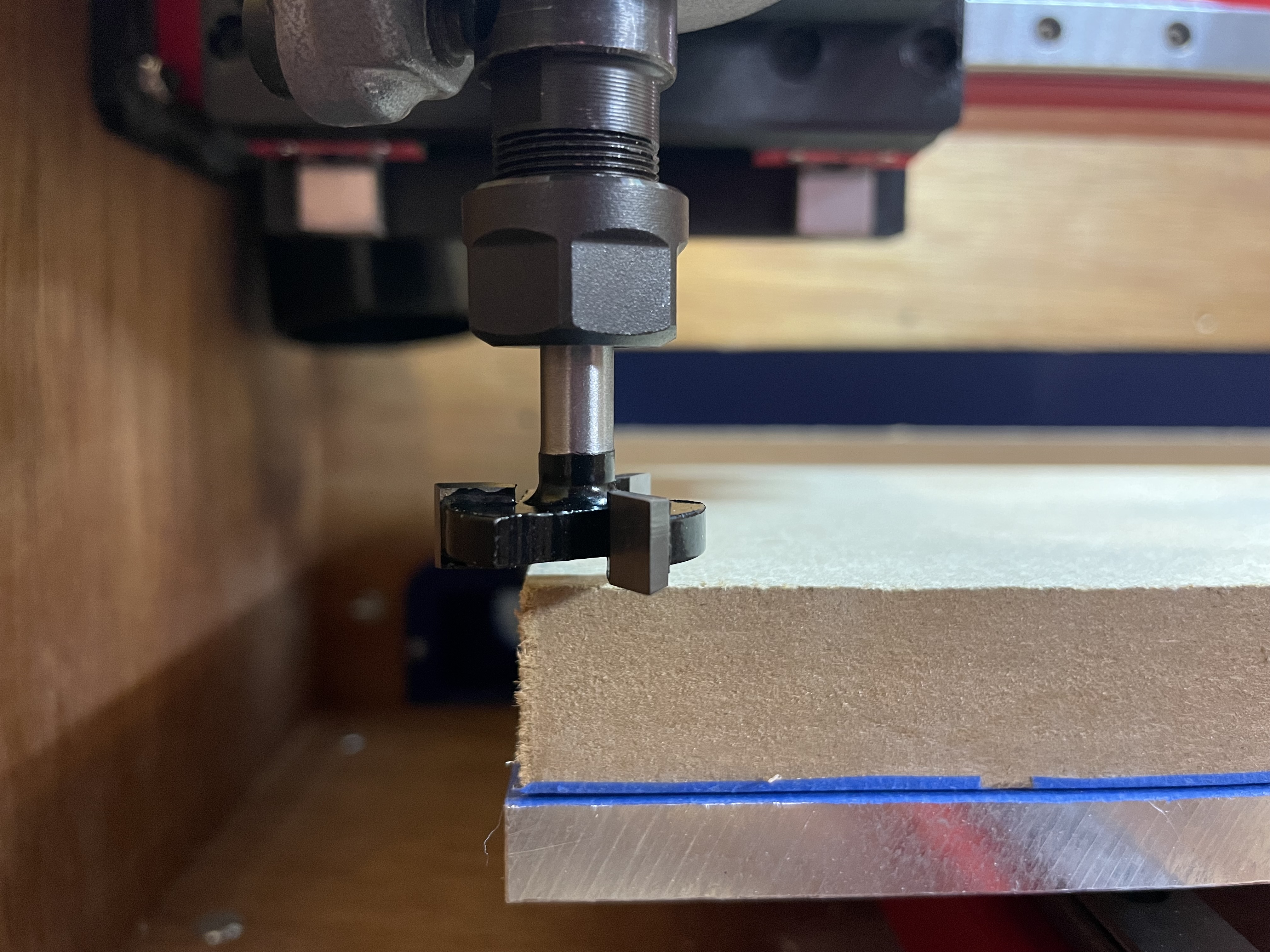
I used a 1” / 25.4mm surfacing endmill. It made quick work of the MDF. The first pass helps determine if your router requires an adjustment and shimming to cut a smooth, flat surface. I required very minimal adjustments. I won’t go into details, as there are many good example videos on YouTube. Here’s an updated version of one video that helped me understand the process: James Dean Tramming